Setting the Camshaft Timing
The Porsche 968 Workshop Manual describes setting the camshaft
timing in section 15. Perhaps something was lost in the translation from
German to English but having recently performed the procedure I found
the manual wording a little short on detail and a tad confusing. But after
consulting various Porsche experts, doing some deep thinking and re-reading
the manual a few times, finally it all fell into place.
So this paper is to share my discoveries, hopefully making things clearer
so you can set up the timing on
your 968 engine with confidence.
The Porsche 968 Workshop Manual referenced here is the
1991 version, section 15.
Following is how I reckon the paragraphs on pages 15-3 through
15-6 should be worded (note I have not checked this lines up with later
print supplements).
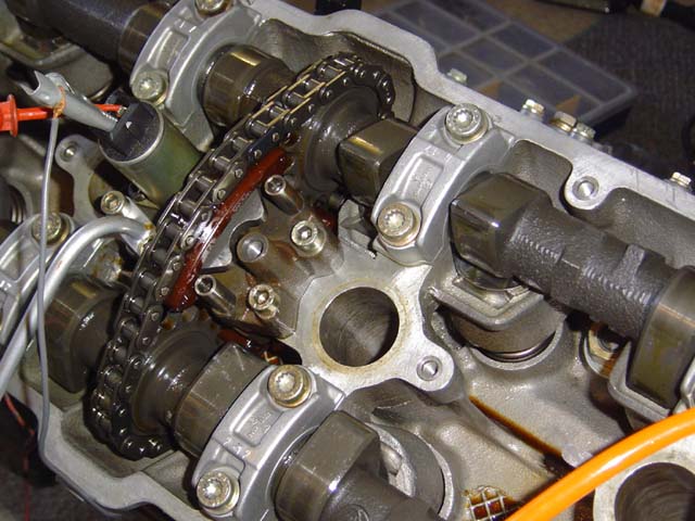
It is assumed you have already removed the covers at engine front and
the camshaft drive belts and gears
are exposed, and the camshaft cover on top of engine is also removed with
camshafts exposed.
(see the drawings on page 15-3).
Regarding engine rotation:- When standing at front of the
car looking at the front of a engine the normal direction of rotation
is clockwise. To rotate the engine I used a 24mm socket on the crankshaft
pulley at the front of the engine, so from here on if I say rotate engine
forwards or clockwise I mean clockwise from this perspective.
1. Rotate the engine in forward
direction until the piston / cylinder #1 is at firing Top Dead Centre
(TDC).
Firing TDC can be found by several means:
| a |
When the mark on the camshaft drive gear lines up with
the mark on the housing as shown in figure 792-15 the engine is at
firing TDC. (The cylinder #1 camshaft lobes should appear approx.
in the positions shown in figure 793-15). |
| b |
If the bell housing and clutch cover are still fitted to the engine,
TDC can be checked by sighting one of the TDC marks on the flywheel.
Note there are two TDC markings set 180o apart on the flywheel. One
marking looks like “OIT” in figure 795-15, the other is
usually a sequence of three closely spaced marks as amplified in figure
794-15. The centre mark of these three is the one you’re looking
to line up via the special sighting hole in the clutch cover plate,
down low in the bell-housing, as shown in the figure 794-15. |
| c |
If bell housing has been removed then you need to use the other
flywheel marks. First mark the top of flywheel immediately above the
“I” in the centre of “OIT” mark, as shown
in figiure 795-15.
Then rotate the engine (forwards / clockwise only) and line your new
mark up with the vertical mark cast into of the back of the crankcase,
as shown in first figure on top of page 15-5. |
Note:
This is a four stroke engine, so the camshaft only rotates 180o
for each full 360o crank rotation.
Hence method a) above is the only one that finds “firing TDC”
for sure. Methods b) and c) find a TDC but this could be the firing
or the non-firing TDC.
Refer to the attached chart to appreciate the difference between
“firing TDC”( A) and “non-firing TDC” (B).
This chart is referred to here as the “Timing Chart”

|
2. Mount two dial gauges
on the cylinder head. Dial gauge #1 requires a straight extension of approx.
200 – 210 mm length to pass right through the spark plug hole onto
the top of piston #1. This is used to determine when piston #1 is precisely
at TDC. Dial gauge #2 requires a bent extension to touch the top of the
hydraulic tappet / lifter for cylinder #1 inlet valve. This gauge must
be mounted so the vertical movement of the dial gauge is in line with
the inlet valve stem axis. Pre-load dial gauge #2 by approx. 3mm.
The manual recommends mounting using “VW 387”
dial gauge mounts. If these are not available, as an alternative approach:
Dial gauges often come with magnetic mount brackets. I found it easy to
bolt some scrap metal brackets onto the aluminium heads, thus providing
solid platforms for the magnets to do their thing and hold the dial gauges
firm and steady.
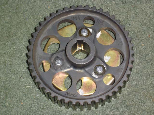
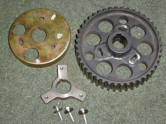
3. Remove the three screws
& spacers holding the distributor rotor. Leave the rotor off, and
fit three temporary screws M5 x 15 to bind the camshaft gear back onto
the backing plate behind it.
Look at the two attached photos of the camshaft drive gear and
the backing plate. The keyway slot in the backing plate is same
size as key in the camshaft, so the backing plate can only be in
one position on the camshaft. But the keyway slot in the drive gear
is almost three times as wide, hence it can be locked into a range
of positions relative to the camshaft.


|
After this whole process is done and the drive gear has
been clamped onto the camshaft (by the large
bolt in gear centre) it’s position relative to camshaft determines
the engine timing.
This is achieved when, with Variocam pressurised, the depression
of inlet valve of cylinder #1, relative to it’s relaxed position,
must be in the range 0.36 to 0.42 mm (0.39 +/- 0.3mm) when the piston
is precisely at non-firing TDC.
This is point (B) in the Timing Chart.
(As an aside, the backing plate has a secondary role. It’s wrapped
edge moves past the camshaft position sensor. There is a break in it’s
circumference that triggers the sensor once for each camshaft rotation).
4. Undo the M10 bolt in centre
of the camshaft drive gear, simultaneously using a counter spanner to
keep the camshaft from rotating. Also loosen the three temporary M5 bolts.
Rotate the engine backwards (anti-clockwise) a short distance, until the
woodruff key in the camshaft meets the end of the keyway slot in the camshaft
drive gear. See figure a bottom right of page 15-5.
5. Tighten the temporary
M5 bolts to 6Nm (4 ft lb) and the central M10 bolt to 40Nm (29 ft lb).
The timing adjustment is now fully to one end of the adjustment range.
The engine is still near cylinder #1 firing TDC, point (A) in the Timing
Chart.
6. Remove the oil feed line
from the top of the Variocam unit. Using a special adaptor (tool 9529
or similar) as shown in figure 799-15 at the top left of page 15-6, feed
pressurised air into the Variocam at a constant 3 bar approx. (44 psi).
This simulates the oil pressure that is present when the engine is running.
Refer to the two photos (Attachments D
&E) of the Variocam.
Both photos were taken with the air pressure applied:- |
One photo is of Variocam with no voltage
applied –the air pressure forces the Variocam piston to the
UP / advanced / “Torque timing” position. In the Timing
Chart this is depicted by the purple arrow near point (B). This
is the engine position we will use later in this procedure. At that
point (B) the advanced timing means the cylinder #1 inlet valve
is just starting to open and the exhaust valve is about to close.

|
The other shows the Variocam with +12V
applied – this releases the air pressure valve inside the
Variocam and puts the piston in the DOWN / retarded / “Basic
timing” position. This is shown by the blue arrow near point
(B) in the Timing Chart.
Note you don’t need to apply voltage to do this procedure.
I only did it to check how the Variocam works.
-100.jpg)
|
| (Aside: There is a typo in the Porsche
968 Technical Specifications booklet at page 16, where it incorrectly
states the intake opens at 7.5o after
TDC in the “Torque Timing” column. As shown correctly
in my chart, and confirmed by the Workshop manual page 15-17, in the
Torque Timing mode the intake valve opens 7.5o before
TDC). |
7. The engine is still near
point (A) in the timing chart. Using dial gauge #1 and small rotation
movements of the engine locate cylinder #1 at precisely firing TDC.
8. Zero the reading on dial
gauge #2 (the inlet tappet).
9. Turn the engine one full
rotation in normal direction (360o clockwise) until Cylinder #1 is near
nonfiring TDC, point (B) in timing chart. As you rotate the engine and
approach point (B) the inlet valve on cylinder #1 will start to open.
Rotate until dial gauge #2 reads between 0.36 and 0.42mm.
Note: Do not rotate against sense of rotation. The Variocam chain tension
mechanism only work for normal direction of engine rotation.
10. Carefully undo the M10
bolt at centre of camshaft drive gear, ensuring the camshaft doesn’t
rotate and the reading on dial gauge #2 stays steady in range. Now the
camshaft is effectively disconnected from the crankshaft, we are ready
to do the fine adjustment of the engine timing.
11. Slowly rotate the engine
until dial gauge #1 indicates the engine is precisely at TDC. The camshaft
lobes for cylinder #4 should appear as in figure 800-15 at the top right
of page 15-6, and the flywheel mark should also align again as shown in
figure 796-15.
12. Tighten the temporary
M5 bolts to 6Nm (4 ft lb) and the central M10 bolt to 65-70Nm (48-52 ft
lb).
13. Your engine timing is
probably done now, but to be sure rotate the engine forward through two
complete revolutions and check the settings again.
--- Congratulations, your Porsche 968 camshafts are now
timed to the factory specification ---
Thanks go to Chris Jennings(Sparky) for this valuable addition
to our technical section.
.jpg)